If you’ve ever received a technical drawing from a supplier and felt unsure where to start, you’re not alone. Engineering drawings follow a strict international language — and once you learn the basics, you can extract critical information quickly and confidently. For procurement teams, site engineers, and equipment buyers, being able to read a drawing means fewer specification errors, faster supplier communication, and better purchasing decisions.
This guide covers everything a non-engineer needs to know: how drawings are structured, what the symbols mean, and how to find the information that matters most for your work.
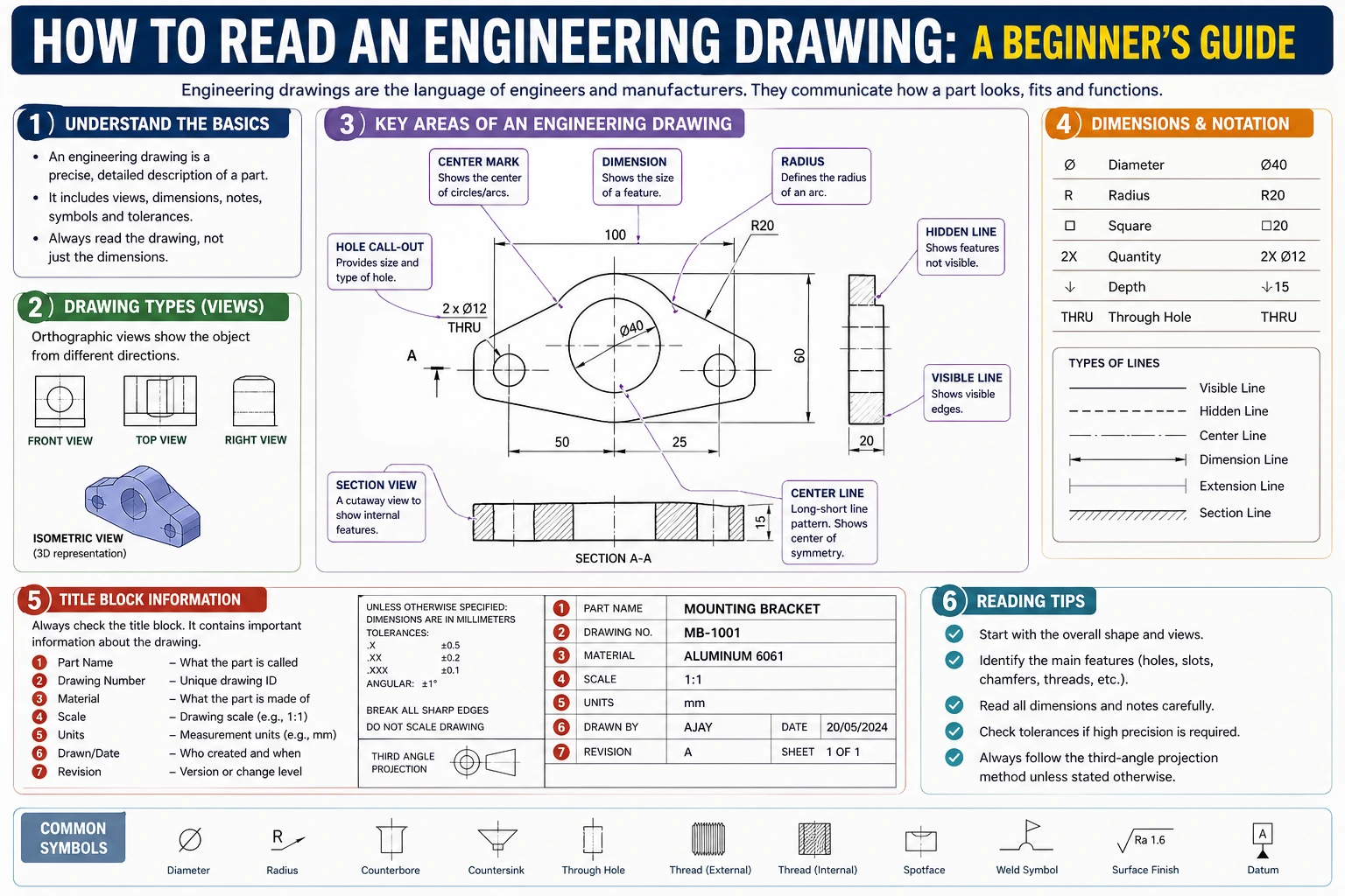
The Title Block: Start Here Every Time
What the Title Block Contains
Every engineering drawing has a title block, usually located in the bottom-right corner. Think of it as the document’s ID card. Before reading anything else on the drawing, review the title block first. It tells you:
- Part name and part number — confirms you have the right drawing
- Drawing scale — for example, 1:10 means the object is drawn ten times smaller than real life
- Revision number — critical for procurement; always confirm you are working from the latest revision
- Material specification — the grade of steel, aluminum, or other material required
- Surface finish — the required roughness or coating
- Tolerances — general tolerance values that apply across the whole drawing unless overridden locally
- Drawn by / approved by / date — traceability information
Why Revision Control Matters
Engineering drawings are living documents. A part may go through five or six revisions before production. If a supplier manufactures from an outdated revision, the result may be dimensionally incorrect — even if their work is technically perfect. Always cross-check the revision number on your drawing against the supplier’s acknowledgment. This single habit prevents a large proportion of specification disputes.
Understanding Views and Projections
First-Angle vs. Third-Angle Projection
Engineering drawings show a three-dimensional object using multiple two-dimensional views. The arrangement of these views follows one of two standards:
- First-Angle Projection (ISO standard): Widely used in Europe, China, and most of Asia. The front view is in the center. The view from the right appears on the left side of the front view. Look for the symbol: a cone shape with the point facing left.
- Third-Angle Projection (ASME standard): Standard in the United States and Canada. The front view is in the center. The view from the right appears on the right side. Look for the symbol: a cone shape with the point facing right.
Confusing these two systems is a common and costly mistake. Always check the projection symbol — typically found in or near the title block — before interpreting the position of views.
The Standard Views
Most drawings use a combination of these views:
- Front view (also called elevation): The primary view, chosen to show the most detail
- Top view (plan view): Looking down on the object
- Side view: Left or right, depending on the projection standard
- Section view: A “cut-through” view that reveals internal features — marked with a cutting-plane line (A-A, B-B, etc.)
- Detail view: An enlarged view of a small area, labeled and circled on the parent view
For crane components and structural steel fabrications, section views are especially important. They reveal internal wall thicknesses, weld preparations, and bore dimensions that are not visible in external views.
Reading Dimensions and Tolerances
How Dimensions Are Shown
Dimensions on an engineering drawing are communicated through dimension lines (thin lines with arrowheads at each end) and extension lines (lines that extend from the part feature to the dimension line). The dimension value sits above or along the dimension line.
Key conventions to know:
- All dimensions are in a stated unit — millimeters (mm) on ISO drawings, inches on ASME drawings. The unit is declared in the title block and is usually not repeated next to each value.
- Reference dimensions are shown in parentheses: (150). These are for information only — they are derived from other dimensions and should not be used to manufacture or inspect.
- Basic dimensions appear in a rectangular box: ⬜50⬜. These define the theoretically exact location or size of a feature, and are always used together with a geometric tolerance.
General vs. Specific Tolerances
Every dimension has a tolerance — the acceptable range of variation. Tolerances appear in two ways:
General tolerances are declared in the title block and apply to any dimension not individually toleranced. For example, a drawing may state “Linear dimensions ±0.5 mm unless otherwise specified,” following ISO 2768 general tolerance classes.
Specific tolerances are written directly next to individual dimensions. They may be shown as:
- Bilateral: 50 ±0.1 (can vary 0.1 mm in either direction)
- Unilateral: 50 +0.2 / 0 (can only increase)
- Limit dimensions: 49.9 / 50.2 (the acceptable range is stated directly)
For procurement purposes, tighter tolerances drive up manufacturing cost. If a supplier quotes significantly higher than expected, reviewing which features carry tight tolerances is a useful starting point for cost discussions.
Key Symbols You Will Encounter
Surface Finish Symbols
A surface finish symbol (√ with a number) indicates the required roughness of a machined surface. The value is usually expressed as Ra (average roughness) in micrometers (µm). A lower Ra value means a smoother surface — and typically higher machining cost. Common values on crane components:
| Ra Value | Typical Application |
|---|---|
| Ra 12.5 | General rough-machined surfaces |
| Ra 3.2 | Bearing seats, mating flanges |
| Ra 1.6 | Precision bores, seal surfaces |
| Ra 0.8 | High-precision running fits |
Weld Symbols
Weld symbols follow ISO 2553 (international) or AWS A2.4 (North American) standards. A weld symbol sits on a horizontal reference line with an arrow pointing to the joint location. The symbol on the arrow side of the line refers to the near side of the joint; a symbol on the other side refers to the far side.
Common weld symbols to recognize:
- Triangle = fillet weld
- V shape = V-groove (butt weld)
- Circle on reference line = weld all around
- MR flag on reference line = field weld (done on-site, not in the shop)
For structural crane components, weld symbols carry safety implications. If a drawing specifies full-penetration groove welds on load-bearing joints, confirm that the fabricator’s welding procedure is qualified accordingly.
GD&T: Geometric Dimensioning and Tolerancing
GD&T is a symbolic language that controls the shape, orientation, and position of features — beyond simple dimensional tolerances. It follows ISO 1101 or ASME Y14.5 standards. GD&T symbols appear in a feature control frame — a rectangular box divided into compartments.
You do not need to master GD&T to work with drawings, but recognizing the most common symbols helps:
| Symbol | Meaning | Why It Matters |
|---|---|---|
| ⊙ | Circularity | Controls roundness of a bore or shaft |
| ∥ | Parallelism | Controls how parallel two surfaces are |
| ⊥ | Perpendicularity | Controls squareness of a face |
| ⊕ | True Position | Controls location of holes or features |
| ↗ | Flatness | Controls surface flatness |
When a drawing has extensive GD&T callouts on critical features, this is a signal that the part requires precision measurement equipment (CMM) for verification — a factor worth confirming with your supplier before ordering.
Practical Reading Checklist for Procurement
When you receive an engineering drawing for a component you are sourcing, work through this sequence:
- Title block first: Confirm part number, revision, material, and units
- Identify the projection standard: First-angle or third-angle
- Locate section and detail views: These usually contain the most critical dimensions
- Note general tolerances: From the title block
- Find tight tolerances and GD&T callouts: These drive cost and require skilled machining or measurement
- Check surface finish requirements: Especially on mating or sliding surfaces
- Review weld symbols on structural parts: Confirm joint type and weld process requirements
- Flag any reference dimensions: Do not pass these to a supplier as manufacturing requirements
This sequence takes less than ten minutes once practiced. It significantly reduces the risk of ordering the wrong specification or receiving a part that cannot be assembled or inspected correctly.
Summary
Reading an engineering drawing is a learnable skill that pays immediate dividends in procurement accuracy and supplier communication. Start with the title block, confirm the projection standard, locate the views that show the features you care about, and pay particular attention to tolerances and surface finish on mating surfaces. You do not need to understand every symbol on a complex drawing — but knowing where to look and what the critical annotations mean puts you in control of the specification.
For crane components in particular, weld symbols and material specifications carry structural safety implications. When in doubt, ask your supplier to walk through the drawing with you — a competent manufacturer will welcome the conversation.
Frequently Asked Questions
Q1: What is the difference between a working drawing and an assembly drawing?
A working drawing (also called a detail drawing) shows a single part with all the dimensions, tolerances, and specifications needed to manufacture it. An assembly drawing shows how multiple parts fit together — it typically includes part numbers, quantities, and reference dimensions for assembly, but not the detailed dimensions needed for manufacturing each individual part. For procurement, both types are relevant: assembly drawings help you confirm the system configuration, while detail drawings are what you send to a fabricator for a quote.
Q2: How do I know which view is the “front” view on a drawing?
The front view is chosen by the designer — it is whatever orientation shows the most useful detail of the part. There is no fixed rule about which physical face of an object becomes the front. The front view is usually the largest and most detailed view on the sheet, and all other views (top, side, section) are arranged around it according to the projection standard. If in doubt, the front view label or the title block notes often clarify the orientation relative to how the part is installed.
Q3: What should I do if a dimension appears to be missing from a drawing?
Never assume a missing dimension. Common causes include drawing errors, intentional omission (where the dimension is controlled by a related part in the assembly), or the dimension being implied by a symmetry note. Contact the drawing originator to request clarification and a formal revision if needed. Do not ask a supplier to estimate or interpolate missing dimensions — this introduces liability and specification risk that is difficult to resolve after manufacture.
Q4: Do all engineering drawings follow the same standard worldwide?
No. The two main families are ISO standards (used in Europe, Asia, and most of the world) and ASME standards (used primarily in North America). They differ in projection angle, dimensioning conventions, weld symbol notation (ISO 2553 vs. AWS A2.4), and GD&T symbology (ISO 1101 vs. ASME Y14.5). When sourcing internationally, confirm which standard the drawing follows and whether your supplier’s team is familiar with it. Misreading a first-angle drawing as third-angle is a well-documented source of assembly errors.
Q5: What is a tolerance stack-up and why does it matter in crane components?
Tolerance stack-up occurs when multiple parts are assembled in sequence, and the individual tolerances on each part add up (or “stack”) in a way that affects the final fit or function. For crane components — such as pin-and-bore joints, runway beam alignments, or gearbox mounting arrangements — a stack-up that exceeds the available clearance can result in binding, misalignment, or stress concentration at joints. When reviewing drawings for a multi-component assembly, check whether the tolerances on mating features have been analyzed for worst-case stack-up, particularly on load-path critical connections.