You’ve just joined a manufacturing company. Your manager mentions “fab shop turnaround” or “forming tolerances” — and you nod, hoping no one notices you have no idea what they mean. That gap is exactly what this article closes.
By the end, you’ll understand what sheet metal fabrication is, how each step in the process works, and why certain decisions — like choosing a cutting method — actually matter on the job. According to industry research, the global sheet metal fabrication market exceeded $15 billion USD and continues growing. This is a skill set worth knowing.
Let’s start from the beginning.
What Is Sheet Metal Fabrication?
The Core Definition
Sheet metal fabrication is the process of transforming flat metal sheets into finished parts or structures through cutting, shaping, and joining. Think of it like origami — except with steel, aluminum, or copper, and powered by industrial machines.
The raw material is a flat sheet, typically 0.5 mm to 6 mm thick (thinner than your finger). The end result might be a car door panel, a server rack enclosure, an HVAC duct, or a kitchen appliance casing.
Why this matters for you: Almost every physical product in manufacturing, construction, or electronics touches sheet metal at some point. Understanding the basics puts you ahead in any cross-functional conversation.
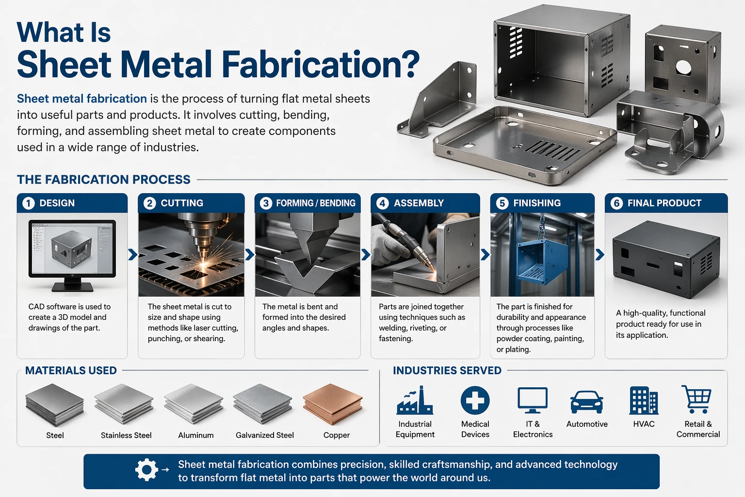
Common Materials Used
Not all metal behaves the same way under force or heat. Here’s a quick breakdown:
| Material | Key Property | Typical Use |
|---|---|---|
| Mild steel | Strong, weldable, affordable | Structural parts, enclosures |
| Stainless steel | Corrosion-resistant | Food equipment, medical devices |
| Aluminum | Lightweight, easy to form | Aerospace, electronics |
| Copper / Brass | High conductivity | Electrical components |
Takeaway: Material choice drives cost, weight, and durability — picking the wrong one adds rework expense down the line.
The Sheet Metal Fabrication Process, Step by Step
The diagram above shows the full flow. Here’s what actually happens at each stage.
Step 1: Design and Engineering
Every job starts with a CAD file (computer-aided design — a digital 3D blueprint). Engineers create a flat “blank” (the flat 2D layout before bending) that accounts for how the metal will deform during forming.
This stage also determines tolerances (the acceptable range of dimensional variation — for example, ±0.1 mm). Tight tolerances mean higher precision, longer machining time, and higher cost.
Why this matters for you: When a production delay happens, it often traces back to a design error found too late. Knowing what a tolerance is helps you ask the right questions early.
Step 2: Cutting
Cutting separates the blank from the raw sheet. There are four main methods:
Laser cutting uses a focused beam of light to slice metal with very high precision. Best for complex shapes and thin materials.
Plasma cutting uses an ionized gas arc. Faster and cheaper than laser, but less precise.
Waterjet cutting uses a high-pressure water stream mixed with abrasive particles. No heat generated — useful for heat-sensitive materials.
Shearing is a mechanical blade action, like giant scissors. Fast and economical for straight cuts only.
Takeaway: The cutting method you choose affects edge quality, speed, and what materials you can work with — it’s not a “just pick one” decision.
Step 3: Forming
Forming reshapes the flat cut piece without removing material. The metal is bent, pressed, or rolled into its final geometry.
The most common method is press brake bending (a machine that presses a punch into the sheet over a V-shaped die to create a precise angle). A press brake operator working on a 90° bend on a 2 mm steel sheet needs to account for springback (the tendency of metal to partially return toward its original flat shape after bending).
Forming is where most dimensional errors occur if tolerances from the design stage weren’t properly planned.
Takeaway: Forming is highly skill-dependent — experienced operators read material behavior in real time, not just off a print.
Joining and Finishing: The Final Two Stages
Step 4: Joining
Once parts are formed, they need to be assembled. The three main joining methods:
Welding — melting the base metal (and often a filler rod) to fuse parts permanently. MIG and TIG are the most common types in sheet metal work.
Riveting — mechanical fasteners that don’t require heat, useful for materials that don’t weld well.
Hardware insertion — press-fit nuts, studs, or standoffs embedded into the sheet for threaded fastening later.
Takeaway: Welding is permanent and strong, but adds heat distortion risk. Fasteners add flexibility for parts that need disassembly.
Step 5: Finishing
Raw fabricated metal needs surface treatment before it’s ready. This step protects the part and gives it its final appearance.
Common finishing options:
- Powder coating — electrostatically applied dry powder, then cured in an oven. Durable and available in any color.
- Anodizing — an electrochemical process that thickens the natural oxide layer on aluminum, improving corrosion resistance.
- Electroplating — depositing a thin layer of another metal (chrome, zinc, nickel) onto the surface for protection or aesthetics.
- Brushing / polishing — mechanical finishing for cosmetic purposes, common on stainless steel appliances.
Takeaway: Finishing isn’t cosmetic afterthought — it determines how long a part survives in its operating environment.
Step 6: Quality Inspection
The final check confirms the part meets the drawing specifications. Inspectors use calipers, coordinate measuring machines (CMMs — automated tools that measure 3D geometry with high accuracy), and go/no-go gauges.
Parts that fall outside tolerance are either reworked or scrapped. This stage is where the cost of upstream errors becomes visible.
Takeaway: Quality inspection is the feedback loop that makes the whole process better — treat every rejection as process data, not just a failure.
Common Misconceptions About Sheet Metal Fabrication
“Fabrication and machining are the same thing”
They’re not. Machining (like CNC milling or turning) removes material from a solid block. Fabrication works with thin sheets and reshapes them. Different equipment, different design rules, different cost structures.
“Laser cutting is always the best option”
Laser cutting is precise, but it’s also slower and more expensive per meter than plasma for thicker materials. The right choice depends on material thickness, edge quality requirements, and volume.
“More finishing = better quality”
Heavy finishing can actually hide defects or add unnecessary weight. Well-fabricated parts often need minimal finishing. If a shop is relying on filler and primer to clean up rough cuts, that’s a process quality issue — not a finishing feature.
What You Can Do Now
After reading this guide, you should be able to: identify the six stages of sheet metal fabrication, explain the difference between cutting methods, and ask informed questions when reviewing a fabrication quote or production schedule.
Your immediate action: Next time you see a fabricated metal product — a server cabinet, an enclosure, a bracket — try to identify the joining method used and which finish was applied. That habit builds faster intuition than any textbook.
Extend your learning: Look into GD&T (Geometric Dimensioning and Tolerancing) — the standardized language engineers use to communicate tolerance requirements on drawings. It’s free to learn the basics through ASME’s published standards summary.
Frequently Asked Questions
Q1: What’s the difference between sheet metal fabrication and structural steel fabrication?
Sheet metal fabrication typically works with thinner gauges (under 6 mm) to produce enclosures, panels, and components. Structural steel fabrication uses much heavier sections — I-beams, channels, and plates — to build load-bearing frameworks like building structures or bridges. The equipment, tolerances, and design rules are quite different. If you’re entering a manufacturing job, clarify which type the shop specializes in before assuming processes are interchangeable.
Q2: How do I know which cutting method a supplier is using, and does it matter?
Yes, it matters. Ask your supplier directly — reputable fabricators will tell you. Laser cutting delivers tighter tolerances and cleaner edges for thin materials. Plasma is faster for thicker stock but leaves a rougher edge that may need secondary grinding. For your first few sourcing conversations, asking about the cutting method signals that you understand quality tradeoffs, which builds supplier trust.
Q3: What does “DFM” mean and why do engineers keep mentioning it?
DFM stands for Design for Manufacturability — the practice of designing parts so they’re easier and cheaper to fabricate. Common DFM rules in sheet metal include: keep bend radii at least equal to material thickness, avoid holes too close to bend lines, and minimize the number of different sheet thicknesses in one assembly. Engineers raise DFM issues early to avoid expensive rework after tooling is set.
Q4: Can sheet metal fabrication handle curved or complex 3D shapes?
Yes, through processes like hydroforming (using fluid pressure to press metal into a die), roll forming (feeding sheet through a series of rollers to produce continuous curved profiles), and deep drawing (stretching a blank into a die to form cups or housings). These are more specialized than standard bending but are common in automotive and consumer appliance manufacturing.
Q5: Is there a standard I should know about for sheet metal tolerances?
ISO 2768 is a widely referenced standard that defines general tolerances for linear and angular dimensions. It has four classes — fine (f), medium (m), coarse (c), and very coarse (v). Most commercial fabrication runs to “medium” unless the drawing specifies otherwise. Knowing this helps you read a drawing or purchase order without needing to ask what every dimension notation means.