Fatigue failure in metals is one of the most dangerous and misunderstood failure modes in crane operations. Unlike a sudden overload, fatigue damage builds silently — often with no visible warning — until a crack propagates and a structural component fails without notice. For crane buyers and fleet managers, understanding metal fatigue is not just a technical matter; it is a safety and budget priority.
This article explains what metal fatigue is, why it happens in cranes specifically, how to spot early warning signs, and what practical steps you can take to extend component life and prevent catastrophic failure.
What Is Fatigue Failure in Metals?
The Basic Mechanism
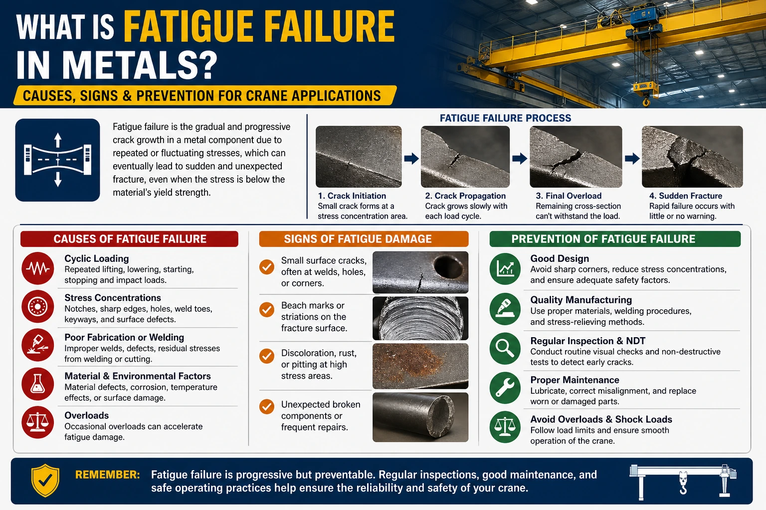
Metal fatigue occurs when a material is subjected to repeated cyclic loading — even at stress levels well below its ultimate tensile strength. Each loading cycle introduces a tiny amount of microscopic damage to the metal’s crystal structure. Over thousands or millions of cycles, this damage accumulates into a small crack. Once a crack initiates, it grows with each subsequent load cycle until the remaining cross-section can no longer carry the load — and the part fractures suddenly.
This is why fatigue failures are often described as “unexpected.” The component may look perfectly intact right up until the moment it breaks.
How It Differs from Static Failure
In static failure, a component breaks because a single load exceeds its strength. In fatigue failure, the component fails after many loads, each one well within the rated capacity. A crane hook, for example, may handle 10,000 lifts at 50% of its Safe Working Load before a fatigue crack becomes critical. This distinction has a direct impact on inspection frequency and replacement schedules.
Why Cranes Are Especially Vulnerable
Cyclic Loading in Daily Operations
Cranes are purpose-built for repetitive work. Every lift cycle — hoist up, travel, lower, release — creates a stress cycle in the boom, runway beams, hook block, wire rope, and structural connections. A busy overhead crane in a manufacturing facility may complete 150–300 lift cycles per shift. That is up to 1,500 cycles per five-day week, or around 75,000 cycles per year. Under these conditions, fatigue life becomes a concrete design parameter, not an abstract concept.
According to FEM (European Materials Handling Federation) classification, cranes are grouped into working classes (A1–A8) based on total number of load cycles and load spectrum. Most industrial workhorses fall in the A4–A6 range, where fatigue design governs structural sizing.
Stress Concentrations: The Crack Initiation Points
Not all areas of a crane structure are equally vulnerable. Fatigue cracks almost always start at stress concentration points — locations where geometry changes create local stress peaks. Common initiation sites include:
- Weld toes on box girder flanges
- Bolt holes in end trucks and joints
- Radii at section changes in hook shanks and pins
- Corrosion pits on wire rope and structural steel
A seemingly minor surface scratch or a poorly executed weld can reduce fatigue life by a factor of 2 to 5 compared to the design expectation.
Material and Environmental Factors
The material’s microstructure, surface finish, and operating environment all influence fatigue behavior. High-strength steels are not automatically more fatigue-resistant — in fact, higher-strength grades can be more sensitive to surface defects. Corrosive environments (coastal salt air, chemical plants, outdoor storage yards) accelerate crack growth by weakening the metal at the crack tip, a mechanism known as corrosion fatigue. Operating temperature also matters: very low temperatures can reduce fracture toughness and accelerate crack propagation.
Key Comparison: Fatigue vs. Static Failure in Crane Components
| Parameter | Static Failure | Fatigue Failure |
|---|---|---|
| Trigger | Single overload event | Accumulated cyclic stress |
| Stress level at failure | Above material strength | Below yield strength |
| Visual warning | Visible deformation | Often none until fracture |
| Typical components affected | Hooks, sheaves (overload) | Welds, wire rope, structural beams |
| Detection method | Visual inspection | NDT (UT, MPI, dye penetrant) |
| Relevant standard | ISO 4308, EN 13001 | EN 13001-3, FEM 1.001 |
How to Identify Early Signs of Metal Fatigue
Visual Inspection: What to Look For
In the early stages, fatigue cracks are rarely visible to the naked eye. However, as cracks grow, several signs become detectable:
- Surface discoloration or fretting marks near welds and joints
- Fine hairline cracks at weld toes, especially under paint or protective coatings
- Rust streaks emanating from a fixed point on structural members, indicating a crack that is collecting moisture
- Unusual deflection in runway beams or bridge girders under normal loads
Non-Destructive Testing (NDT)
Reliable early detection requires NDT methods. The most commonly used techniques in crane maintenance include:
- Magnetic Particle Inspection (MPI): Effective for surface and near-surface cracks in ferromagnetic components. Widely used on hook blocks, lifting beams, and welds.
- Ultrasonic Testing (UT): Can detect internal cracks in structural welds and thick sections. Suitable for bridge girder inspections per EN 13001.
- Dye Penetrant Testing (DPT): Low-cost method for surface cracks on non-magnetic components such as aluminum or stainless steel hardware.
A practical inspection program should schedule NDT intervals based on the crane’s working class, operating history, and environment — not simply on calendar time.
Prevention Strategies That Work
Design-Stage Choices
The most cost-effective fatigue prevention happens at the design stage. Specifying a crane with the correct FEM/ISO working class for your actual duty cycle is the single most impactful decision. An undersized working class means the crane’s structural components were not sized for the actual number of load cycles — and fatigue life will be exhausted prematurely.
Additional design measures include:
- Using full-penetration welds rather than fillet welds at primary load-carrying joints
- Specifying post-weld treatment (grinding, shot peening) at high-stress weld toes
- Avoiding abrupt section changes in structural members
Operational Controls
Even the best-designed crane ages faster when operated outside its intended parameters. Practical operational controls that reduce fatigue accumulation:
- Avoid shock loading (sudden jerking during hoist or travel)
- Stay within rated capacity on every lift — even brief overloads are disproportionately damaging
- Distribute lifts evenly across the crane’s runway span where possible, rather than repeatedly loading the same mid-span position
- Log operating cycles to track actual duty versus design duty
Maintenance and Inspection Schedule
A proactive maintenance program aligned with ISO 9927-1 (Cranes — Inspections) provides a structured framework for fatigue monitoring. Key elements:
- Routine visual checks at shift start
- Periodic detailed inspections (quarterly or per manufacturer’s schedule)
- NDT inspection intervals based on working class and observed condition
- Documented replacement criteria for wire rope, hooks, and structural components
Summary and Action Steps
Fatigue failure in metals is a predictable and manageable risk — provided it is treated with the same discipline as other engineering hazards. For crane operators and procurement managers, the practical takeaway is straightforward:
- Match the crane’s working class to your real duty cycle before purchase.
- Implement an NDT-based inspection program — visual-only inspections will miss fatigue cracks until they are dangerously large.
- Train operators to avoid shock loading and to report any unusual noises, deflections, or surface marks.
- Keep cycle logs so you can track fatigue life consumption against design limits.
Metal fatigue does not announce itself. But with the right selection criteria, inspection tools, and operational discipline, it is entirely preventable.
Frequently Asked Questions
Q1: What is the most common location for fatigue cracks to form on an overhead crane?
Fatigue cracks in overhead cranes most commonly initiate at weld toes on the box girder’s bottom flange — the area under the highest tensile bending stress during a lift. Other frequent initiation sites include the hook shank, end truck connections, and any location where a notch, hole, or abrupt section change creates a stress concentration. These areas should be prioritized in every inspection cycle.
Q2: How does wire rope fatigue differ from structural steel fatigue?
Wire rope fatigue accumulates through a different mechanism than structural fatigue. In wire rope, repeated bending over sheaves and drums causes individual wires to fatigue-fracture from the inside out, often before any visible broken wires appear on the outer surface. This is why rope replacement criteria under standards such as ISO 4309 are based on a combination of visible broken wires, diameter reduction, and the number of operating cycles — not visual condition alone.
Q3: Can a crane be repaired after fatigue cracking is found?
In some cases, yes — but repair acceptability depends on the crack’s location, size, and the structural component involved. Cracks in secondary structural elements may be repaired by grinding out the crack and re-welding to an approved procedure. Cracks in primary load-carrying members (main girder flanges, hook shanks, lifting pins) typically require component replacement and a formal engineering assessment before the crane returns to service. Any repair should be documented and followed by NDT verification.
Q4: How does the operating environment affect fatigue life in practice?
Harsh environments shorten fatigue life significantly. In coastal or high-humidity settings, corrosion attack at the crack tip (corrosion fatigue) can accelerate crack growth rates by two to five times compared to a controlled indoor environment. Chemical exposure — acids, chlorides, and cleaning agents — has a similar effect. For cranes operating outdoors or in corrosive conditions, inspection intervals should be shortened and surface protection (coatings, galvanizing, sacrificial anodes) maintained rigorously.
Q5: What standards govern fatigue design and inspection for industrial cranes?
Several key standards apply: EN 13001 (Crane safety — general design) covers fatigue load combinations and structural utilization for new equipment in the EU market. FEM 1.001 provides working class classifications and fatigue design curves widely used by European manufacturers. ISO 9927-1 establishes inspection frameworks for in-service cranes. For wire rope specifically, ISO 4309 defines discard criteria. When evaluating a crane’s suitability for a specific application, confirming compliance with these standards — rather than relying solely on a supplier’s rated capacity — is strongly recommended.