You’re reviewing a motor specification sheet and the term “gear ratio” keeps appearing — but nobody has explained what that actually means for the machine’s performance. This is a common situation for professionals stepping into mechanical or industrial roles for the first time.
By the end of this article, you’ll know what a gearbox does, how its core mechanics work, which type suits which application, and what three parameters drive correct selection. According to industry data, improper gearbox selection accounts for over 30% of preventable drivetrain failures in industrial machinery — making this one of the most practical concepts to get right early.
Read on for the clearest breakdown you’ll find.
What a Gearbox Does — and Why It Exists
The Core Job
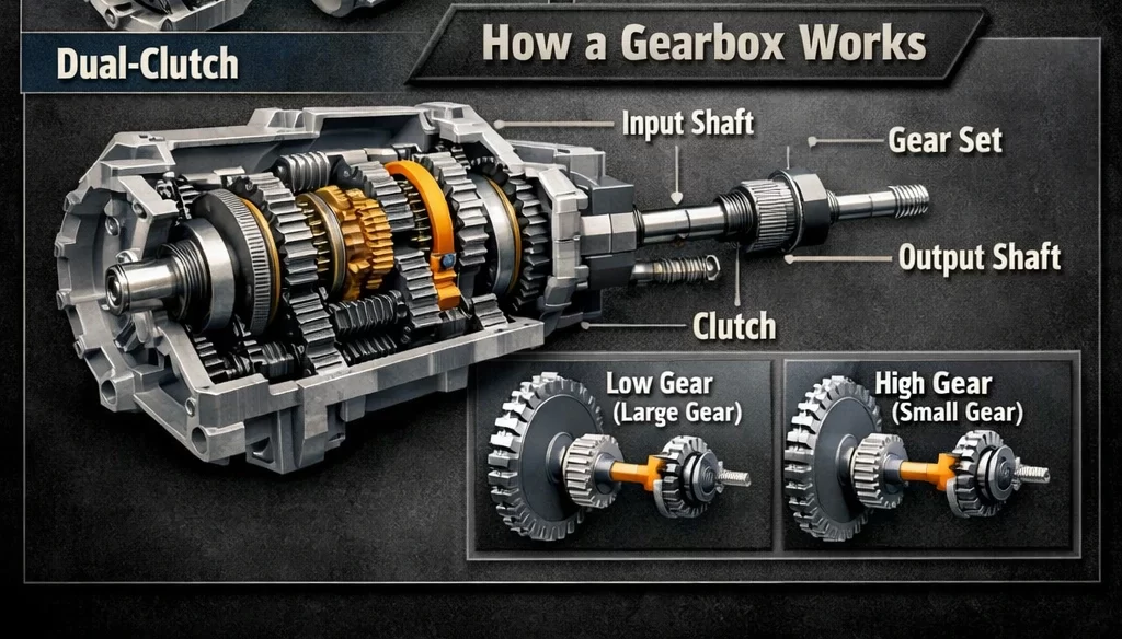
A gearbox is a mechanical device that transfers power from a motor to a driven machine while changing the relationship between speed and torque (rotational force). It sits between the power source and the output shaft, acting as a translator between what the motor provides and what the load actually needs.
The best analogy is a bicycle. Shifting to a low gear while climbing a hill lets you pedal faster with less effort — the wheel turns slower, but with more force. A gearbox does exactly this for industrial machines, converting the motor’s high-speed, low-torque output into the low-speed, high-torque input that most loads require.
The Speed–Torque Trade-off
Speed and torque move in opposite directions when power is held constant. A gearbox that cuts output speed in half roughly doubles the output torque — minus small friction losses. This exchange is governed by the gear ratio (the number of times the input shaft rotates for every single rotation of the output shaft).
A gear ratio of 10:1 means the input turns ten times for every one output revolution. The output runs ten times slower and delivers approximately ten times the torque.
Why this matters for you: Selecting the wrong gear ratio means the machine either lacks the force to move its load or runs so slowly it bottlenecks production.
What a Gearbox Is Not
A gearbox does not generate power — it redistributes it. And it is not a variable-speed drive. A standard industrial gearbox operates at a fixed ratio. If variable output speed is needed, that requires a separate variable frequency drive (VFD) on the motor side.
Core takeaway: A gearbox matches a motor’s output characteristics to a load’s input requirements. Getting this match right is the entire point of gearbox selection.
The 5 Main Gearbox Types
Spur and Helical Gearboxes
Spur gearboxes use straight-cut gear teeth on parallel shafts. They are simple, inexpensive, and efficient — but noisy at speed, because the teeth engage all at once rather than gradually.
Helical gearboxes solve the noise problem with angled teeth that engage progressively. The result is smoother, quieter operation and higher load capacity. Helical designs are the most common type found in industrial conveyor drives, compressors, and pump systems.
Bevel Gearboxes
Bevel gearboxes redirect power between shafts that meet at an angle — almost always 90 degrees. The gears are cone-shaped, with teeth cut on the cone surface. They are the go-to solution wherever a right-angle drive is needed, such as in mixers, printing machines, and steel mill equipment.
Spiral bevel variants use curved teeth for the same progressive-engagement advantage that helical gears have over spur gears.
Worm Gearboxes
A worm gearbox achieves very high gear ratios — commonly 10:1 to 100:1 — in a single compact stage. The worm (a threaded shaft) drives a wheel gear at a 90-degree axis. In most designs, the worm can drive the wheel but the wheel cannot back-drive the worm, creating a natural self-locking effect under power loss.
This self-locking property makes worm gearboxes standard equipment in hoists, lifting platforms, and gate drives. The trade-off is efficiency: sliding contact between worm and wheel generates heat, with efficiency typically ranging from 50% to 90% depending on ratio and build quality.
Planetary Gearboxes
A planetary gearbox distributes load across multiple “planet” gears orbiting a central “sun” gear inside an outer “ring” gear. Because several gear meshes share the load simultaneously, planetary units deliver very high torque density in a coaxial (input and output on the same axis), compact package.
They are the preferred choice wherever precision, compactness, and high torque-to-size ratio are required — servo drives, robotics, and CNC machine tool spindles.
| Type | Shaft Orientation | Typical Ratio Range | Best For | Main Limitation |
|---|---|---|---|---|
| Spur | Parallel | 1:1 – 6:1 per stage | Simple low-speed drives | Noisy at high RPM |
| Helical | Parallel | 1:1 – 10:1 per stage | General industrial use | Axial thrust forces |
| Bevel | 90° intersecting | 1:1 – 6:1 | Direction-change applications | Complex to manufacture |
| Worm | 90° perpendicular | 10:1 – 100:1 | High ratio, self-locking needed | Low efficiency |
| Planetary | Coaxial | 3:1 – 100:1+ | Precision, high torque density | Higher unit cost |
Core takeaway: Type selection comes down to three questions — what shaft orientation do you need, what ratio range is required, and does the application demand self-locking or precision low-backlash performance?
How to Evaluate and Select a Gearbox
The Three Numbers You Must Establish First
Output torque requirement. Calculate the torque the gearbox must deliver to move the load — in Newton-meters (Nm). Do not estimate. Errors here propagate through every other selection decision.
Required gear ratio. Divide motor speed (RPM) by the required output speed. If the motor runs at 1,450 RPM and the load needs 145 RPM, the ratio is 10:1.
Service factor. A multiplier applied to the calculated torque to account for real-world conditions. Shock loading, frequent starts and stops, or 24-hour continuous operation each push the service factor higher — typically between 1.25 and 2.5. A gearbox rated at exactly the calculated torque with no service factor applied is undersized for almost any real application.
Key Technical Parameters at a Glance
| Parameter | Plain English Meaning | Typical Unit |
|---|---|---|
| Gear ratio | Input RPM ÷ output RPM | e.g., 10:1 |
| Output torque rating | Max torque deliverable continuously | Nm |
| Thermal power rating | Max power before overheating under continuous load | kW |
| Backlash | Rotational play at output shaft when direction reverses | arcminutes |
| Efficiency | Percentage of input power reaching the output shaft | % |
| IP rating | Protection level against dust and liquid ingress | e.g., IP65 |
The Two Mistakes That Cause Most Field Failures
Selecting on ratio alone. Two gearboxes with identical ratios but different torque ratings are not interchangeable. The output torque rating, checked against your service-factored requirement, is the primary specification — not the ratio.
Ignoring the thermal power rating. In continuous-duty applications, the thermal limit is frequently lower than the mechanical torque limit. A gearbox that can deliver 500 Nm mechanically may only sustain 300 Nm continuously before overheating. Always cross-check both ratings for 24/7 or high-cycle applications.
Core takeaway: Correct gearbox selection takes twenty minutes of calculation. Incorrect selection costs days of downtime. The service factor is the most skipped step — and the most consequential.
After Reading This, You Should Now Be Able To…
Explain what a gearbox does and why the speed-torque relationship is its central function. Identify the five main types and the application conditions that favor each. And walk through the three-step selection process — output torque, gear ratio, service factor — without missing the step that most people skip.
Your next action: Find the nameplate on any gearbox in your facility. Locate the ratio, the output torque rating, and the service factor. Match those numbers against what you’ve just read. Connecting real hardware to the framework is the fastest way to make this knowledge stick.
Extend your learning: The AGMA (American Gear Manufacturers Association) publishes free introductory overviews at agma.org — their fundamentals section on gear geometry and rating is accessible without a technical background and is the natural next step from this article.
Frequently Asked Questions
Q1: What is the difference between a gearbox and a transmission?
A transmission is a gearbox that can change its ratio during operation — through manual shifting or automatic control. A standard industrial gearbox runs at a fixed ratio. In automotive engineering, “transmission” is the default term. In industrial and mechanical engineering, “gearbox” is more common. The underlying mechanics are identical: gears transmitting torque between shafts. If someone asks whether a conveyor gearbox is a transmission, the technically correct answer is no — unless it has selectable ratios.
Q2: How do I know when a gearbox needs replacement rather than repair?
Repair makes sense for isolated failures — a single damaged bearing, a worn seal, one cracked gear tooth — when the housing and shaft geometry are still within tolerance. Replacement is the better call when the housing is cracked, multiple gear meshes are damaged, shaft journals are worn beyond spec, or repair cost exceeds roughly 60–70% of a new unit. Age alone is not a decisive factor; load history and oil maintenance records matter more.
Q3: What does backlash mean, and when should I care about it?
Backlash is the small angular play between meshing teeth when the load direction reverses. For most conveyors, pumps, and mixing equipment, a few arcminutes of backlash has no measurable effect on performance. For CNC machines, robotic arms, or servo-driven positioning systems, even small backlash introduces positioning error that accumulates over cycles. Precision planetary units are manufactured to low-backlash specifications — under 3 arcminutes — for exactly these applications.
Q4: Can a gearbox increase speed instead of reducing it?
Yes. A step-up gearbox has a ratio below 1:1 — for example, 1:5 — so the output shaft spins faster than the input with proportionally less torque. The most common real-world application is wind turbine drivetrains, where a slowly rotating turbine rotor must be sped up significantly to reach the operating RPM of the connected generator.
Q5: How often should gearbox oil be changed?
It depends on oil type and operating conditions. Mineral gear oil in moderate-duty service typically needs changing every 2,000 operating hours. Synthetic oil in a sealed unit under normal conditions can extend to 8,000–10,000 hours. High temperatures, water contamination, or heavy shock loading all shorten intervals. The manufacturer’s maintenance schedule is the baseline — but if oil analysis shows metal particles or viscosity breakdown before the scheduled interval, change it early regardless.