A shaft coupling connects two rotating shafts to transmit torque from one to the other. Simple in concept — but the wrong choice causes vibration, misalignment damage, and premature equipment failure. Getting it right from the start saves significant cost downstream.
This guide explains how shaft couplings work, walks through the main types, and gives you a practical framework for selecting the right one for your application.
What Does a Shaft Coupling Actually Do?
At its core, a shaft coupling joins a drive shaft (from a motor, engine, or gearbox) to a driven shaft (a pump, conveyor, compressor, etc.). Its job is to transmit torque reliably while managing the realities of real-world installation — which rarely involves two perfectly aligned shafts.
Three Functions Every Coupling Must Perform
Most shaft couplings serve three roles simultaneously:
Torque transmission — transferring rotational force from one shaft to the next without slippage or energy loss.
Misalignment compensation — absorbing angular, parallel, or axial misalignment between the two shaft centerlines. Even small amounts of misalignment, left unaddressed, generate bearing loads and accelerate wear.
Vibration and shock damping — protecting connected equipment from load spikes, startup shock, and operational vibration. This is especially relevant in machinery with variable loads or frequent start-stop cycles.
Not every coupling type handles all three equally well. That trade-off is the core of the selection decision.
Main Types of Shaft Couplings
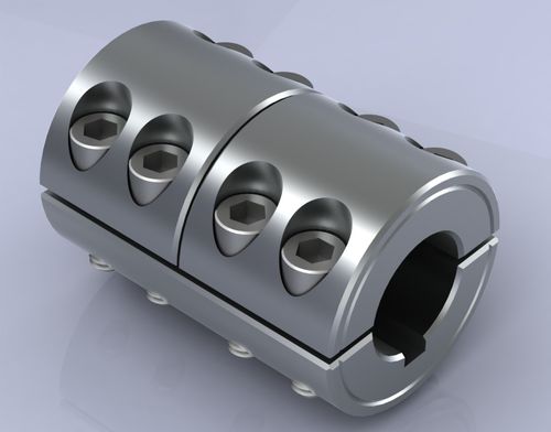
Rigid Shaft Couplings
Rigid couplings connect two shafts with no flexibility. They transmit torque efficiently and are simple to install — but they tolerate zero misalignment. Any offset between shafts transfers directly as stress into bearings and seals.
They’re appropriate in applications where shafts are precisely aligned and will stay that way: short drive systems, encoder mounts, or situations where a fixed mechanical connection is required by design.
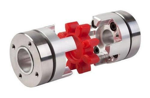
Flexible Shaft Couplings
Flexible couplings are the most widely used category in industrial applications. They accommodate moderate misalignment and absorb vibration through a flexible element — rubber, polyurethane, or a elastomeric spider insert — positioned between the two coupling halves.
Common variants include jaw couplings, tire couplings, and pin-and-bush couplings. Each handles misalignment and shock loads slightly differently, but all share the same fundamental advantage: they protect connected equipment from forces that rigid connections would transmit directly.
Jaw couplings, for example, are a popular choice for pump-motor connections. The elastomeric spider insert between the jaws absorbs shock and provides electrical isolation between shafts — a useful secondary benefit.
Gear Couplings
Gear couplings use meshing gear teeth to transmit torque. They handle high torque loads and moderate misalignment, making them a standard choice in heavy industrial drives — steel mills, paper machines, large conveyor systems.
They require lubrication (grease-packed or oil-bath), which adds a maintenance requirement absent in elastomeric designs. The trade-off is high torque density in a compact form.
Disc and Diaphragm Couplings
Disc couplings use thin metal disc packs to transmit torque while flexing to accommodate misalignment. They’re torsionally stiff — meaning they transmit torque with minimal windup — while still handling angular and axial movement.
This combination makes them well-suited for servo drives, precision positioning systems, and high-speed applications where torsional accuracy matters. They contain no wear elements, which reduces maintenance requirements over time.
Universal Joints (Cardan Couplings)
Universal joints transmit torque between shafts at a significant angle — up to 45 degrees in some configurations. They’re a standard solution when drive and driven shafts cannot be aligned axially: agricultural equipment, vehicle driveshafts, and certain industrial drive systems.
Single universal joints introduce velocity variation through the rotation cycle. Double universal joint configurations (Cardan shafts) cancel this effect and deliver smooth torque transmission across the angle.
How to Select the Right Shaft Coupling
Step 1 — Define the Torque Requirement
Start with the rated torque of the drive system — then apply a service factor. This factor accounts for shock loading, start-stop frequency, and load variability. A smooth, constant load might use a service factor of 1.0–1.25. A system with frequent starts or impact loading may require 1.5–2.5 or higher.
The selected coupling must have a rated torque capacity that meets or exceeds: nominal torque × service factor.
Step 2 — Identify the Misalignment Conditions
Measure or estimate the actual misalignment present in your installation. Misalignment has three forms:
| Misalignment Type | Description | Typical Range Tolerated |
|---|---|---|
| Angular | Shafts meet at an angle | 0.5°– 5° depending on type |
| Parallel (radial) | Shaft centerlines are offset | 0.1 mm – 2 mm |
| Axial | Shafts move toward/away from each other | 0.5 mm – 5 mm |
No coupling type handles all three forms equally. Flexible elastomeric couplings manage parallel and angular well. Disc couplings handle angular and axial. Universal joints handle large angular offsets. Match the coupling type to the dominant misalignment condition in your system.
Step 3 — Consider Speed, Environment, and Service Life
Higher operating speeds demand better balance. At speeds above 3,000 RPM, coupling balance grade becomes a specification — unbalanced couplings generate centrifugal forces that feed directly into bearing loads.
Environmental conditions matter too. Elastomeric elements degrade in oil, high temperature, or chemical exposure. Metal-element couplings (disc, gear, universal joint) are more chemically robust but add mechanical complexity.
For applications where maintenance access is limited, consider couplings with no wear elements and no lubrication requirements — disc couplings and certain diaphragm designs serve this need well.
Common Selection Mistakes to Avoid
Ignoring service factors — rating a coupling to nominal torque without accounting for dynamic loads is one of the most common causes of premature coupling failure.
Over-specifying flexibility — a highly flexible coupling in a precision servo system introduces torsional windup that degrades positioning accuracy. Match flexibility to what the application actually needs.
Forgetting bore size and keyway requirements — confirm shaft diameter, keyway dimensions, and hub bore specifications before ordering. Coupling selection and mechanical fit are separate but equally important checks.
Treating all misalignment the same — parallel and angular misalignment load couplings differently. A coupling that handles one well may not handle the other adequately.
Summary
A shaft coupling is a small component with an outsized impact on system reliability. The right selection comes down to four factors: torque requirement (with service factor applied), misalignment type and magnitude, operating speed, and environmental conditions.
Rigid couplings suit precise, fixed alignments. Flexible couplings handle the majority of general industrial applications. Gear couplings serve high-torque heavy drives. Disc and diaphragm couplings fit precision and high-speed systems. Universal joints solve large angular offset problems.
Work through these criteria systematically, and the right coupling type for your application becomes straightforward.
FAQ
Q1: What is the most common type of shaft coupling used in industrial applications?
Flexible elastomeric couplings — particularly jaw couplings — are among the most widely used in general industrial settings. They accommodate moderate misalignment, absorb vibration and shock, and require no lubrication. Their elastomeric insert (spider) acts as the wear element and can typically be replaced without moving connected equipment. They suit pump-motor drives, conveyor systems, compressors, and a wide range of rotating machinery where some misalignment and occasional shock loading are expected in normal operation.
Q2: How much misalignment can a shaft coupling handle?
It depends entirely on the coupling type. Rigid couplings tolerate essentially zero misalignment. Flexible jaw couplings typically handle angular misalignment up to 1°and parallel offset up to 0.5 mm, depending on size. Universal joints can manage angular offsets up to 30–45 degrees. Always check the manufacturer’s published misalignment limits for the specific model — operating at or near the maximum limit consistently will shorten service life. The goal should be to minimize misalignment through good installation practice, using the coupling to handle residual offset rather than compensate for poor alignment.
Q3: What is a service factor, and why does it matter for coupling selection?
A service factor is a multiplier applied to the nominal system torque to account for dynamic loads beyond steady-state operation. Shock loads during startup, variable loads, frequent reversals, and vibration all increase the effective torque a coupling experiences. A coupling sized only to nominal torque without a service factor will be under-rated for real operating conditions. Typical service factors range from 1.0 for smooth constant loads to 2.5 or higher for heavy shock applications. Applying the correct service factor at the selection stage is one of the most effective ways to prevent premature coupling failure.
Q4: When should I use a disc coupling instead of a jaw coupling?
Choose a disc coupling when torsional stiffness is a priority — servo drives, precision positioning systems, and high-speed applications where angular accuracy matters. Disc couplings transmit torque with minimal torsional windup, which preserves positioning accuracy that an elastomeric jaw coupling would compromise. They also contain no wear elements and require no lubrication, reducing maintenance needs over time. The trade-off is lower shock absorption compared to elastomeric designs. If your application involves impact loads or frequent start-stop cycles, a jaw coupling’s damping capacity is often more valuable than the torsional precision of a disc coupling.
Q5: How do I know when a shaft coupling needs to be replaced?
Common warning signs include visible cracking or hardening of elastomeric elements, unusual vibration or noise during operation, backlash or rotational play between connected shafts, and evidence of wear debris around the coupling area. For elastomeric jaw couplings, the spider insert is the primary wear element and should be inspected at regular service intervals — typically annually or per the manufacturer’s recommendation. Metal-element couplings (disc, gear) should be inspected for fatigue cracking, fretting corrosion on disc packs, and lubrication condition. Replacing a worn coupling element proactively is significantly less costly than bearing or seal damage caused by a failed coupling.